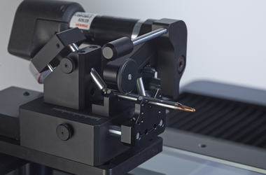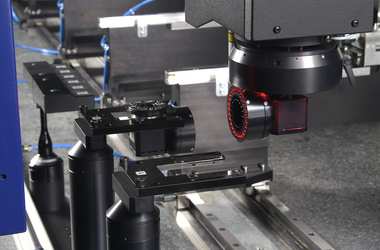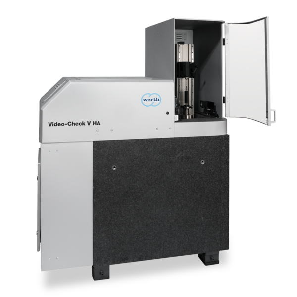


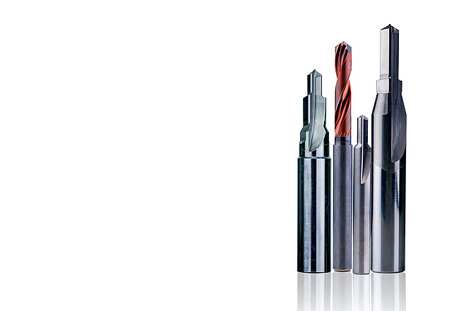
Step drills can be used, for example, to produce a through hole, a small blind hole and a chamfer in a single machining step. The drill tip geometry depends on the material in which the bore is to be made. In addition to the drill tip geometry, the diameters of all steps, the core run, the taper, step lengths and step angles are measured. Depending on the drill application, the tolerances vary in the range from 5 µm to 20 µm and therefore require a low to very low measurement uncertainty. The measuring time plays a subordinate role.
-
Applications
- 3D free-form workpieces
- Extruded workpieces
- Moulds
- Semiconductor workpieces
- Lithographic structures
- Metal-plastic composite workpieces
- Prismatic workpieces
- Punched and bent parts
- Packaging
- Shaft-hub connections
- Shafts and axes
- Workpieces with micro-features
- Workpieces with optical functional surfaces
- Tools with geometrically determined cutting edges
- Tools with geometrically indeterminate cutting edges
- Gear wheels
- Cylindrical workpieces
- Industries
- Products
-
Service
- Programming services
- Measuring machine capability analysis, measurement process capability and traceability
- Measurement services with multi-sensor systems or computed tomography
- Repair
- Maintenance
- Calibration
- Installation, relocation and commissioning
- Retrofitting and updates
- Training courses
- Downloads
- About Werth
- Careers
- Foundation
- Publications
- Downloads